How to do the BJL Mod
Rick Detlefsen 09 Dec 2003(rev...13may2012-parts list)
I got intrigued with downloading games, demos, and utilities to the Atari Jaguar during some of the JYBOLAC chats. As game cartridges and CDs were encrypted, they were difficult to get onto the Jag to test and play. BJL(Behind Jaggy Lines) is by no means the first such system(rom and adapter/cable), but appears to be the fastest. It only requires a PC, ST, STe, or Falcon (TT?), unlike others that can require expensive and difficult to find development systems.
Bastian Schick, Lars Baumstark, and others created the Jag to parallel port (NOT centronics) connection method and software for Jag, PC/ST(e)/Falcon. They have made this available to anyone who wishes to build and install it. Some cartridges are already BJL aware.
This mod adds an eprom on top of the existing rom. An alternative removes the existing rom. Do not attempt this if you do not have soldering and project skills. Any damage, including killing your Jaguar is totally your responsibility!
How to install the mod:
Opening the Jaguar:remove the 4 screws on the bottom. The top shell will pull off.
Removing the shield pcb:There are 4 more screws, two at the cartridge socket and two more in line near the front. Remove. The shielded pcb will lift out, back first.
Opening the shield:Pry up all of the tabs on top on the shield. The top will come off, but will take careful prying.
Now is a good time to use startic precautions...ground yourself.
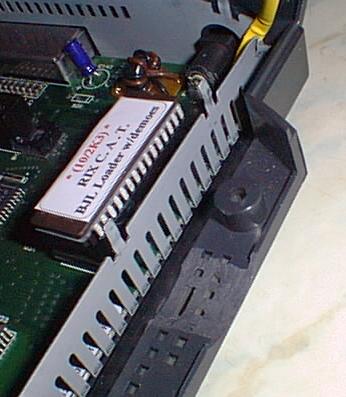
Note:Installing the Eprom:
The pins of the eprom may need bending in, use a table top, carefully. With you having touched a ground, place the eprom on one side of the socket. Press a little and roll the other side in. Make sure the notch faces the rear. Once inserted, look at the pins..they should be straight and in the socket.
There are three ways to do this:
METHOD 1:Piggyback:
Solder tin each of the 32 pins of the rom and the eprom. Notice the notch of the rom towards the back of the Jaguar. With it to the back, the pin to the left is number 1, the pin to the right is 32, numbered counter-clockwise around the rom. Unsolder or cut off close to the pcb pin 22 of the rom. Next, position the eprom on top of the rom aligning the pins, making sure none short adjacent pins, the notches(or pin 1 dot) on both go towards the back. Tack solder diagonal corners. Adjust if needed. Once the pins match, solder all except 22. Should be easy since all are solder tinned.
METHOD 2:Board Socket:
Unsolder the rom, do trace repairs, install socket with notch towards back. Continue with Method 1.
METHOD 3:Eprom socket:
Solder tin each of the 32 pins of the rom and the socket. Notice the notch of the rom towards the back of the Jaguar. With it to the back, the pin to the left is number 1, the pin to the right is 32, numbered counter-clockwise around the rom. Unsolder or cut off close to the pcb pin 22 of the rom. Cut off pin 22 of the socket. Next, position the socket on top of the rom aligning the pins, making sure none short adjacent pins, the notches(or pin 1 dot) on both go towards the back. Tack solder diagonal corners. Adjust if needed. Pins 22 of socket and rom should NOT touch. Once the pins match, solder all(except pin 22). Should be easy since all are solder tinned. Lift pin 22 of the eprom, insert eprom into socket. I like this one since it lets the eprom get replaced/reprogrammed as needed.
Wiring:
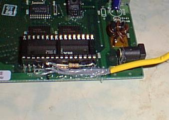
Now is a good time to strip about 1/8 inch from each of the six wire ends. One end of the center wire gets soldered to the pad on the pcb where pin 22 of the rom used to go. A resistor goes to the raised pin 22 of each. The other end goes to pin 32. The two remaining wire ends go to each pin 22. Slip the small tubing over the wire. It will slide down and protect the wire where it exits the shielding. A little hot glue around the pins and wires will help secure them.
01feb2012:I am using a different switch, installing is essentially the same.
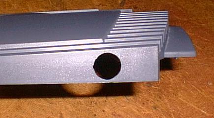
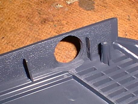
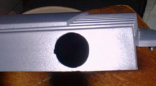
This part gets more difficult. Placing the switch. I didn't like the bat handle switches. They just don't go with the Jaguar. But this is a little harder to put in. I choose the rear right side, near the rom. A 7/8 inch hole is drilled and filed between the last two bars molded on the side, but against the rear bar. Closing the two halves, the bottom will need some filing as well. Start small. Frequently try installing the switch to see what needs filing/sanding. Gently make the hole bigger. The switch will eventually fit. But take care not to come through the top or bottom. It will get thin. You can file the notch to keep the switch from turning in the hole, or secure the inside sides only with some hot glue.
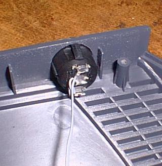
Trim the three contacts on the switch way down so they won't short against the shield. Solder tin. Put it in. Then solder the other end of the wires..center lead to center terminal. Follow the lead from the eprom and solder to the bottom switch terminal. Rom lead to the top.
Carefully lay out the jaguar, plug in a cartridge, power, and TV lead. Turn on the Jaguar. You should get the familiar animated logo. As long as the screen is black, if nothing happens, turn off, flip switch, and turn on. If you get the logo, the socket install is a success. If nothing happens or you get a red screen, you have a wiring error/short.
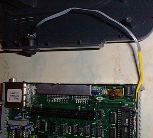
With the switch in the eprom position, turn ON the Jaguar. If you get the BJL main screen, you have successfully installed the eprom mod. Turn OFF the Jaguar. Remove any attached cables. With the pcb in the lower shield(still), put it in the case bottom. Route the wire thru the corner, bending down enough of the shield for the wire to fit. The tubing will protect the wire. Now is the time to put the case top on and make sure the switch contacts don't touch, you can put a piece of electrical tape on the shield if desired. If all is well, replace the 4 screws removed from the pcb. Replace the shield, bend down the tabs. Put the case top on, and replace the 4 bottom screws.
You are all done with the mod.
Want to get your own parts?
You will need a programmed(bjl1060.img 121K[inc demos] or bjl1051.img 12k) 32 pin eprom, number 27C010-120 or similar
2 1/4 watt resistors, 4.7K(yellow,purple,red,gold)
1 32 pin low profile socket(if you plan on replacing the rom, a machined socket may be better)
1 SPDT switch
1 length of three conductor wire, 12 inches.
1 protective tubing
And of course, the adapter/cable to connect it to a PC/STE/Falcon.
Here is the schematic to do that:
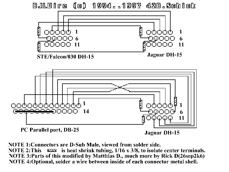
Note that the ST must use the parallel adapter. Probably easiest for any of the machines.
Take me to the How to Use page.
Take me to my BJL main page..